
Saturday, January 12, 2013
Rendered Using BPR/Photoshop with Yiannis Tyropolis
AMBIENT LIGHTING- OCCLUSION: I use the Flat Material with BPR AO and very high settings so I a very smooth ambient shading. When you use this pass as an occlusion you don't need to have so much detail but I don't use it like that.
KEY LIGHT - Basic Material with one light with relatively hard shadows, no specular on Material and no Ambient on the Light Palette. Shadow Strength to 1.
FILL- BOUNCE LIGHT- Like the Key Light with softer shadows
REFLECTION - I used this for specular highlights, I think the material is HDRI_SKIN MATERIAL(of course it's not HDR) but any material with an image mapped would do. No shadows no Occlusion. The same direction of light like the Key
FRESNEL PASS - This the Fresnel Overlay Material. When I was setting up the passes I didn't know there was a material like that. As I was exploring I noticed that . You could do that differently, but this is by far the easiest .Very handy. no shadows or AO
DEPTH - self- explanatory
COLOR - Flat Color Mat. There you have your polypainting or textures
CHANNEL MATTES - Flat Color Mat. There you polypaint- fill your separate subtools with 100% blue, green, red color so you can separate them in post.
MASK- self- explanatory
BACK SCATTERING - I used a similar setup like the default shader on the SSS demoSoldier. I turn off the non SSS materials, No Shadows or Ao. I used the default position for the backlight. The settings change by the scale and resolution* of the image
FRONT SCATTERING - Same Settings like Back Scattering but I used the direction of the Keylight.
The Document bkg is set to black or white depending on whether you Multiply, Add or Screen.
Compositing made with Shake and the workflow is similar in all node based Apps (Fusion, Nuke, etc) Does anybody care for the Node Tree?
I'm replicating the comp in PS so it's more convenient for most users to explain. You can have identical results.
about the comp...
A is the Upper Hierarchy, a Masks group, a diffuseLighting group, spec Reflection group, an SSS group and a Fresnel group, you can see the blending modes.
B is the middle hierarchy
Masks - these are all the masks of the different objects .With the ChannelsA/B/C you can separate every object, for example if you combine the green channel of the Channel Matte A an the green channel of the Channel Matte B you have the shirt.
Diffuse Lighting - these are the most important groups. You can control the lighting ratio by changing their opacity.
Spec Reflection - these control the different specular reflectivity of every object.
SubsurfaceScattering- you can see the objects that have this effect, by the name of the groups, every object has different intensity.
Fresnel - these groups control the different diffuse lighting reflection at the edges of the objects. You can see the color correction at the top of the hierarchy, that changes the hue, the same for every object.
C. is the lower hierarchy. every object masked.
Diffuse Lighting Subgroup - every group the contains the equivalent Light pass,multiplied by the Color pass, if there is color Balance adjustment layer is to control the hue of the light itself, like changing the color in the ZB Lights sub palette (It's not supported by BPR).
Spec Reflection Subgroup - every group contains the Reflection pass multiplied by the Ambient Lighting- occlusion pass.
SubsurfaceScattering Subgroup - every group contains the Front Scattering pass color corrected(color balance) screened by the BackScattering pass. Gamma corrected(levels) and intensity corrected( layer opacity).
Fresnel Subgroup - every group contains the Fresnel pass multiplied by the Ambient Lighting- occlusion pass.
I 'd like to point, that renders with Sss, Ao, and Shadow need to change when you Scale-Frame the tool in a document, so whenever you change resolution and framing you have to change settings. Also the subpixel quality varies the result beside the antialising.
*whenever you don't see a blending mode, means it's the same as above
Thursday, January 3, 2013
Metabaron Nameless ZBrush Render Tutorial
Once the sculpture is finshed I made retopologies, for the cloth are hand made retopology and for the head since is going to be no animated model is just a ReMesh to have a equal polygon surface for the polypaint.
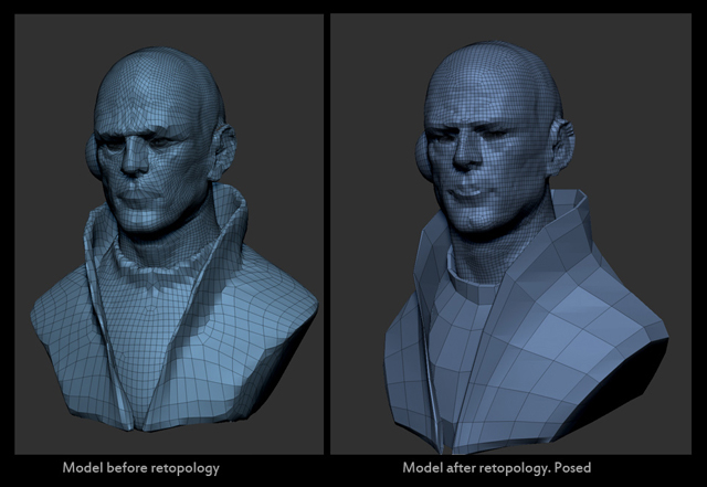
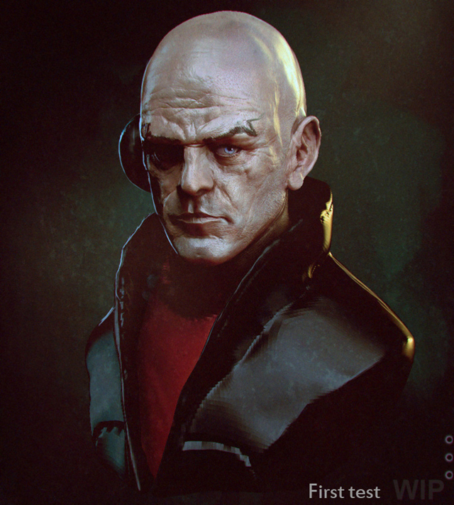
This a test to use as a guide to my self for the final looking, no taking much care about topology and also add some over paint for details to add after.
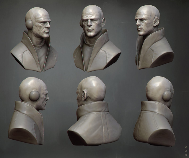
This is the model with all the details on it ready to paint and shader it for the render.
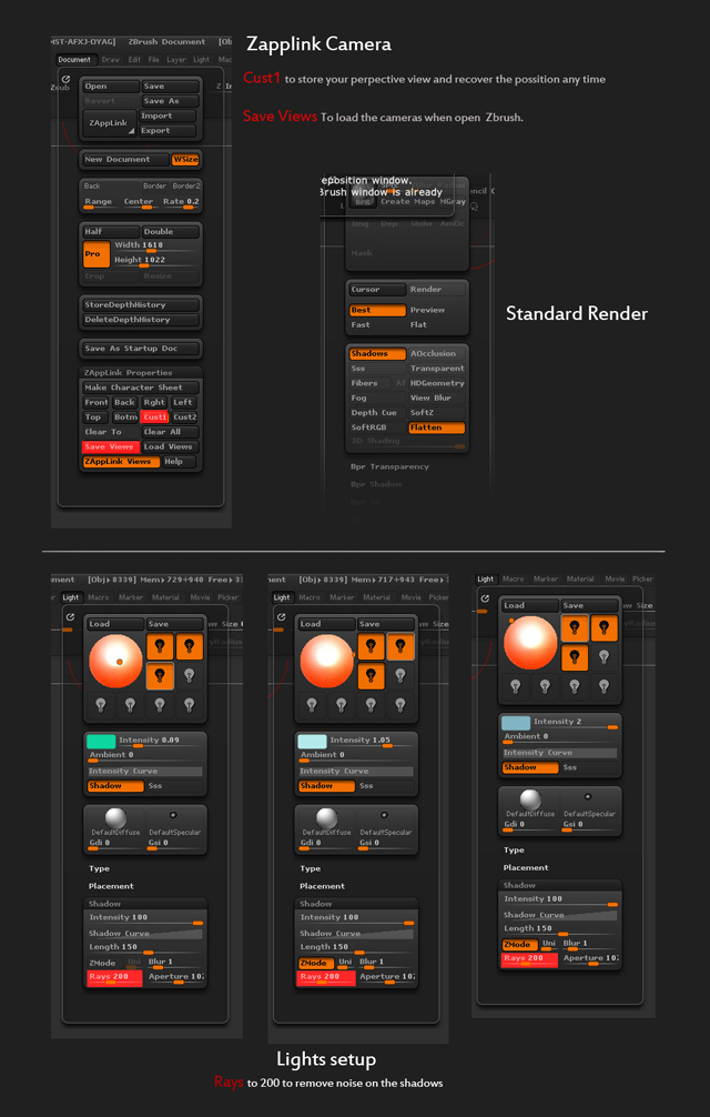
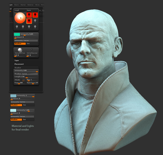
On this image is explained how to save the camera view to have any time is needed. Also is used a standard render with standard render. And the configuration of the three lights for the render.
This is the result of the material and lights.
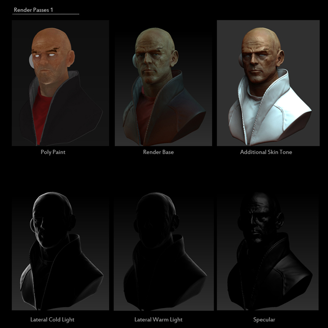
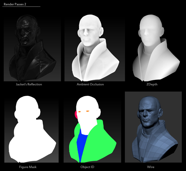
Here are all the render passes using different materials and adding some lights to achieve the final result.
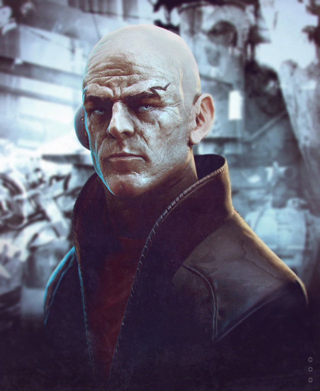
The final render, composed in photoshop.

Best Preview Render
Best Preview Render
 ZBrush Artist: Steve Warner
The new Best Preview Render (or BPR) will render your model using high quality anti-aliasing at the full document size. Use of the AAHalf button is not necessary when using this rendering mode. BPR will render all SubTools, with polyframes displayed if that is activated and also provides several new render options including subsurface scattering and fibers effects.
The main BPR controls, including the BPR button, are at the top of the Render palette. The BPR button and SPix slider are also at the top right of the default UI.

An example of multi-pass rendering using several MatCaps, ambient occlusion, shadows and depth. By Igor Catto.
Contents[hide] |
Render Main options

- BPR button (hotkey Shift+R) executes the render. The BPR only works for a model in Edit mode and no 2.5D effects are rendered. During the render BPR will clear any background pixols but these will reappear as soon as you click the canvas.
- SPix controls the quality of the anti-aliasing: The higher the value the better the quality but the longer it will take to render the image. Set the slider to 0 for no anti-aliasing and quickest render time - this is useful when trying out other effects.
- VBlur Radius controls the amount of View Blur: This is a temporary effect unrelated to BPR and does not show in exported images.
- Create Maps: Turn on this button to create various maps for compositing in an image editor such as Photoshop. After the BPR has finished, click an icon to export that map. For the Shadow and Ambient Occlusion maps the relevant option must be turned on lower down in the Render palette.
- MGray: This option instructs ZBrush to produce Shadow and AO maps at maximum grayscale range.
Render options panel

Activate a switch to include that option in the render. Not all options are available in BPR; for example, the Glow materials will only work correctly with the original Best Render. BPR will take account of Shadows, AOcclusion, Sss, Transparent, Fibers, HDGeometry and Depth Cue.
Below the render options panel are separate submenus for adjusting different BPR options. A submenu only becomes active when the relevant option is switched on.

A simple render with Ambient Occlusion, Shadows and Fibers enabled. Image by Satoshi Arakawa.
BPR Transparency

The BPR transparency menu includes all settings related to using transparency with the BPR. With BPR it is possible for a model to be seen through some of its SubTools. (In other words, for a model to be self-transparent.) For example, eyeglass lenses can be made transparent so that the character’s face can be viewed through them. To specify which SubTools you wish to be transparent you must select the third icon (in the Tool >> SubTool list) for them.
- Strength: controls the Transparency effect by surface normals. A higher value will give greater transparency.
- NFactor: surface normals factor. This controls the falloff between transparent and opaque parts of the mesh due to normal direction. A setting of 0 means that all parts of the mesh will be transparent; a setting of 1 means that only normals directly facing the viewer will be transparent.
- ByColor: controls Transparency effect through color intensity. A higher value will give greater transparency.
- CFactor - color intensity factor: Higher values give greater distinction between colors. A setting of 0 gives no distinction between colors and with a ByColor setting of 1 the mesh will be completely transparent. A setting of 4 will give greatest variation with black areas fully transparent and white areas fully opaque.
- Refract - the amount of refraction: A setting of 0 gives no refraction effect, while a setting of 1 gives the greatest refraction.
- RFactor - refraction factor: Higher values give a more exaggerated refraction, effectively multiplying the setting of the Refract slider. Set to a high value for a magnifying lens effect.
BPR Shadow

The BPR shadow menu includes all settings related to rendering shadows when using the BPR. Shadows can be activated for individual lights - see the Lights section of the online documentation for more details.
- Strength: sets the shadow strength; higher values give a stronger shadow.
- S Color: sets the shadow color. Click on the button and select the desired color from the color chooser. Color is not included in the shadow map created when the Create Maps option is on.
- Rays: the number of rays used in the shadows calculation. A higher number will give softer shadows, depending on the Angle setting. Increasing the number of rays will increase render time.
- Angle - the maximum angle through which the rays are generated: Higher values give softer, less focused shadows. A setting of 360 with a high number of rays will give an effect close to ambient occlusion.
- Res - the shadow resolution in pixels: This figure is effectively the image size (independent of document size) that ZBrush uses internally to calculate the shadows. Lower settings will render more quickly while higher settings will give greater accuracy. Sometimes a lower value can give the desired result with less processing overhead - for example, when soft shadows are required.
- Blur - shadow blur radius in pixels: Higher values give softer, more blurred shadows. This is related to the Res slider and should be adjusted in tandem for the same effect. For example, if the Res slider value is changed from 500 to 1000, a Blur value of 4 should also be doubled to 8.
- VDepth - view depth offset in pixels: The shadow calculation is offset towards (with negative values) or away from (with positive values) the viewer. Negative settings can increase the intensity of the light and the shadows; positive values create more overall shadow.
- LDepth - light depth offset in pixels: The shadow calculation is offset towards (with negative values) or away from (with positive values) the light source. Negative settings can increase the intensity of the light and the shadows; positive values create more over all shadow.
- Spd - sub-pixel depth calculations: Gives greater shadow accuracy. Normally left on but turning off will speed up render times when experimenting.
BPR Ambient Occlusion (AO)

The BPR Ambient Occlusion (BPR Ao) menu includes all settings related to rendering ambient occlusion when using the BPR. Combined with the default shadows, it will give more depth to your model.
- Strength: Sets the strength of the ambient occlusion effect; higher values give a stronger effect.
- Color - Click to set the color of the ambient occlusion: Color is not included in the AO map created when the Create Maps option is on.
- Rays - the number of rays used in the ambient occlusion calculation: A higher number will give softer AO, depending on the Angle setting. Increasing ray number will increase render time.
- Angle: Normally this should be left at 360 but reducing the value will narrow the AO effect in relation to light direction. A setting of 1 will only use the single light as the AO source.
- Res - the AO resolution in pixels: This figure is effectively the image size (independent of document size) that ZBrush uses internally to calculate the ambient occlusion. Lower settings will render more quickly while higher settings will give greater accuracy. Sometimes a lower value can give the desired result with less processing overhead - for example, when a weak AO effect is required.
- Blur - AO blur radius in pixels: Higher values give softer, more blurred ambient occlusion. This is related to the Res slider and should be adjusted in tandem for the same effect. For example, if the Res slider value is changed from 500 to 1000, a Blur value of 4 should also be doubled to 8.
- VDepth - view depth offset in pixels: The AO calculation is offset towards (with negative values) or away from (with positive values) the viewer.
- LDepth - lights depth offset in pixels: The AO calculation is offset towards (with negative values) or away from (with positive values) the light sources.
- Spd - sub-pixel depth calculations: Gives greater AO accuracy. Normally left on but turning off will speed up render times when experimenting.
- Gamma - ambient occlusion gamma: Gamma is similar to the brightness of the AO effect. Lower values will give a darker over all ambient occlusion, higher values will be lighter. A setting of 5 should work for most situations.
ZBrush Artist - Steve Warner
BPR Subsurface Scattering (SSS)

The BPR Subsurface Scattering (BPR Sss) menu includes all settings related to rendering Subsurface Scattering when using the BPR. This effect will simulate the light absorption visible in some material types: skin, milk, marble, special plastics and more.
Subsurface scattering (or SSS) can be activated for individual lights - see the Lights section for more details in the online documentation. SSS is also controlled through the material modifiers which provide color selection and adjustment of blend effects. See the Materials section for further details.
- SSS Across Subtools: all subtools are taken into consideration when calculating subsurface scattering. If this button is off, SSS is calculated as if each subtool is lit individually.
- Rays - the number of rays used in the subsurface scattering calculation: A higher number will give softer SSS, depending on the Angle setting. Increasing the number of rays will also increase render time.
- Angle: Normally this should be left at 360 but reducing the value will narrow the subsurface scattering effect in relation to light direction.
- Res - the SSS resolution in pixels: This figure is effectively the image size (independent of document size) that ZBrush uses internally to calculate the subsurface scattering. Lower settings will render more quickly while higher settings will give greater accuracy. Sometimes a lower value can give the desired result with less processing overhead - for example, when a weak SSS effect is required.
- Blur - SSS blur radius in pixels: Higher values give softer, more blurred subsurface scattering. This is related to the Res slider and should be adjusted in tandem for the same effect. For example, if the Res slider value is changed from 500 to 1000, a Blur value of 4 should also be doubled to 8.
- VDepth - view depth offset in pixels: The SSS calculation is offset towards (with negative values) or away from (with positive values) the viewer.
- LDepth - lights depth offset in pixels: The SSS calculation is offset towards (with negative values) or away from (with positive values) the light sources. Settings towards the light source tend to create greater SSS, settings away from the light result in less SSS.
- Spd - sub-pixel depth calculations: Gives greater SSS accuracy. Normally left on but turning off will speed up render times when experimenting.
Depth cue
 ZBrush Artist:Ofer Alon
An example of a SubSurface Scattering render, combined with Depth Cue
The BPR can include Depth Cue. Depth cue causes the image to be rendered with different blur levels at different depths. This can be used to simulate the effect of a lens that focuses sharply at only one depth, or atmospheric haze that causes distant objects to appear less distinct.

- Depth Cue Alpha: A texture can be selected to modify the depth cue effect. Click the Depth Cue Alpha patch to access the texture sub-palette and choose a texture. It will be converted to grayscale and stretched to fill the entire canvas area. The luminance of the alpha will determine the intensity of the depth cue at that location. White areas give the strongest depth cue effect, black areas give no effect. Useful for restricting the depth cue effect to a selected area of the canvas.
- Intensity: Sets the intensity of the blur at its farthest point.
- Softness: The number of pixels averaged to produce the blur. Higher numbers produce more blur.
- Depth1: Depth1 is the near point of the depth cue effect. There is no blurring at this distance. The blurring begins as depth increases. Type in the Z depth directly or click and drag from the slider to the canvas to set the value; pick an object at the depth where you want the depth cue to begin and release the mouse button.
- Depth2: Depth 2 is the far point of the depth cue effect. There is full blurring at this distance. Type in the Z depth directly or click and drag from the slider to the canvas to pick a depth.
- Depth Cue Curve: Adjust the curve to change the intensity of the depth cue between the near point (Depth1) and far point (Depth2).
Notes: By setting a high depth cue intensity at each end of the curve and a low intensity at an intermediate point, you can achieve a “lens effect”, where depths both in front of and behind the focal plane of the virtual camera’s lens are blurred.
To preview the depth cue and find the best settings for the Depth1 and Depth2, activate the Fog and change its settings. When the fog looks like the depth cue you are looking for, copy its settings to the equivalent locations in the Depth cue menu.
Fog

The BPR can include Fog. Fog allows the render to have a cloud fog effect over the entire image. The start and end points of the fog are controlled by the Depth1 and Depth2 sliders.
- Intensity: determines the overall strength of the fog effect.
- Depth1: determines the nearest distance along the Z-axis at which objects are displayed without fog. Between the Depth1 value and the Depth2 value, items are rendered with increasing fog applied. You can specify values in this slider or you can click on it and drag to the canvas to pick a depth value.
- Depth2: determines the furthest distance along the Z-axis beyond which all items are displayed with maximum fog applied. From the Depth1 value to the Depth2 value, items are rendered with increasing fog applied. You can specify values in this slider or you can click here and drag to the canvas to pick a depth value.
- Fog Color 1: selects the color of the fog at the Depth1 point and nearer. If a texture is chosen in the Fog Texture picker, this color is ignored.
- Fog Color 2: selects the color of the fog at the Depth2 point and beyond. If a texture is chosen in the Fog Texture picker, this color is ignored.
- Fog Texture: clicking this selector gives a pop-up of the Texture palette to select the texture which will be used to color the fog. This setting overrides the selections in the Fog Color 1 and Fog Color 2 pickers. To clear it, select ‘Texture Off’.
- Fog Alpha: clicking this selector gives a pop-up to select a texture which will be converted to grayscale based on the texture’s color intensity values and used to map the fog effect. Lighter areas define the places where the effect is strongest.
Fog Curve: defines the way in which the fog effect is applied along the Z-axis. By default, from the Depth1 value to the Depth2 value items are rendered with increasing fog applied. This curve defines the amount of fog at each point between the Depth1 and the Depth2 values.
Subscribe to:
Posts (Atom)